The playback unit is self-contained and is designed to be connected to the antenna terminals of any
domestic American color television receiver to provide playback of replicated videodiscs. It employs an
optical technique to read the videodisc that does not require any physical contact between the read head and
the videodisc. This non-contact system provides for long life of both the videodisc and the read head and it
also permits freeze-framing without any wear penalties. The essential elements of the playback unit include
the following:
- An optical system that directs and focuses a low-power helium-neon laser beam to a small read spot on
the surface of the videodisc and then collects the reflected optical energy and directs it to a single
photo detector.
- A means of rotating the videodisc at the correct speed.
- A means of positioning the read spot on the videodisc surface which acquires and locks on to the
spiral data track.
- A means of maintaining the optical system in focus on the surface of the videodisc.
- The necessary electronics to process the signals for the television receiver.
- The controls, control electronics and power supplied to operate and power the unit.
- A functional and decorative enclosure to house the unit.
|
3.1 Optical System
The playback optical system is shown in Fig.4. The light source used is a low-power helium-neon laser tube.
The laser tube has a nominal output power of 1 milliwatt which is single mode (TEM00) and
linearly polarized. The laser beam is initially directed by two mirrors which are adjustable for alignment
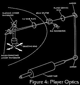 purposes. The laser beam is then expanded to fill the back of the objective lens by a plano-convex lens.
This beam expanding lens is adjustable along its axis to provide for fine focus of the optical system. The
beam is then transmitted through a specially coated beam splitter. The direction of the laser beam
polarization is such that most of the beam will pass through the beam splitter. A quarter-wave plate changes
the beam polarization from plane to circular. The beam is then directed into the back of the objective by two
mirror transducers which consist of mirrors that can be rotated by piezoelectric bender motors. These
rotations produce a corresponding motion of the read spot on the disc surface. One transducer is used to move
the read spot in a radial direction to provide the high speed tracking corrections required to follow the data
track. The other mirror transducer causes the read spot to move in a tangential direction on the videodisc to
provide the time base corrections. These high speed tracking and time base corrections are required because
of videodisc eccentricity, mechanical vibrations, etc.
purposes. The laser beam is then expanded to fill the back of the objective lens by a plano-convex lens.
This beam expanding lens is adjustable along its axis to provide for fine focus of the optical system. The
beam is then transmitted through a specially coated beam splitter. The direction of the laser beam
polarization is such that most of the beam will pass through the beam splitter. A quarter-wave plate changes
the beam polarization from plane to circular. The beam is then directed into the back of the objective by two
mirror transducers which consist of mirrors that can be rotated by piezoelectric bender motors. These
rotations produce a corresponding motion of the read spot on the disc surface. One transducer is used to move
the read spot in a radial direction to provide the high speed tracking corrections required to follow the data
track. The other mirror transducer causes the read spot to move in a tangential direction on the videodisc to
provide the time base corrections. These high speed tracking and time base corrections are required because
of videodisc eccentricity, mechanical vibrations, etc.
The objective lens which focuses the laser beam to a small spot on the surface of the videodisc has a numerical
aperture of .35 and an effective focal length of approximately 12 millimeters. The laser light that is
reflected from the surface of the videodisc is collected by the objective lens and returned along substantially
the same path that the incoming beam traveled. When the reflected beam passes through the quarter-wave plate,
it is changed again to plane polarized light, but it is polarized at a right angle to the direction of the
incoming laser beam. The reflected beam is then reflected by the beam splitter to the PIN photodiode detector
where the optical signal is converted to an electrical signal for processing by the electronics. The use of
the plane polarized laser tube, the specially coated beam splitter, and the quarter-wave plate results in a
high efficiency optical system that minimizes the reflected signal that is fed back into the laser cavity. |
3.2 Playback Signal-to-Noise Ratio
The optical efficiency of the player was measured by comparing the energy returned to the PIN diode by: (1) a
large "land" area on a videodisc; (2) a series of bumps having 2.2 micrometer wavelength, corresponding to
an FM frequency of 6.75 mHz at a 3 inch radius. The return from the large land was 10.0%; from a bump 3.0%;
from the space between bumps 5.5%. Hence, if a player with a 1 milliwatt laser was reading a 2.2 micrometer
recording, a peak to peak signal of .025 milliwatt would return to the PIN diode. This in turn would yield a
photocurrent of 2x10⁻⁶ amp RMS. The noise floor of such a system would be
determined by photon shot effects, thermal effects, laser noise and pre-amp noise. Measurements indicate that
the thermal and pre-amp noise dominate and are roughly equal. They give rise to a noise current of
2x10⁻⁸ amp RMS so that the FM SNR would be 100:1 or 40 db assuming perfectly
recorded bumps having a 2.2 micrometer wavelength. When demodulated this FM SNR yields a video SNR of better
than 58 db which does not limit the playback quality. The actual playback video SNR is limited by replica
disc quality and is presently better than 40 db. |
3.3 Disc Rotation
The videodisc is mounted on a turntable that is rotated at 1798.2 revolutions per minute by an electric motor.
The speed of the turntable is sensed by a tachometer that consists of a phototransistor and light emitting
diode that are located on either side of an incremental encoder disc that is mounted on the turntable spindle.
The belt driven turntable spindle is powered by an universal type motor, powered from the ac power lines using
a triac. The triac is controlled by a phase locked loop control circuit that compares the tachometer output
frequency with the counted down output of the 3.58 mHz crystal controlled oscillator in the signal processing
electronics. Thus, the spindle drive motor is brought to and maintained at an angular velocity that produces
zero mean error between the frequency produced by the tachometer wheel and that of the divided crystal
oscillator. This is the rate required to make the frequency of the color signal, and hence the horizontal
sync signal, within the range of the time base correction servo. |
3.4 Tracking Servo
Due to possible non-concentricity of the replicated disc and the turntable, replicated disc out-of-roundness
and vibration, the read beam and the tracks relative positions do not remain constant. The tracking servo
controls the radial position of the read beam in a manner that results in constant read beam position within
the track. The ratio of opened to closed loop gain in the control loop would reduce a simple eccentricity of
0.1 millimeters to a reading error of less than 0.15 micrometers. The maximum trackable eccentricity is about
0.25 millimeters, but as a practical matter, the replicated discs will have eccentricities less than half that
value.
Since the overall development objective was aimed at a reasonably priced consumer product, a simple tracking
and information reading system requiring only a single photo-surface for all functions combined was developed
(after considering a variety of techniques). This not only minimizes the cost of photo-detectors and their
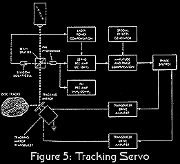 associated electronics, but even more importantly, reduces to one the number of optical paths that must be
critically aligned and registered during the manufacturing process. The tracking servo technique is
illustrated in Fig. 5. A single PIN photodiode is used to recover the tracking servo and video signals. A
limited bandwidth, high gain dc pre-amp outputs a signal that is a function of read beam position within a
track. It is clear that this signal is also directly proportional to laser power output. Since laser output
power is influenced by a variety of conditions, some means of compensation is required for long term stable
tracking. A portion of the direct beam is directed onto an inexpensive silicon solar cell with the cell
output used as a compensating signal in the servo pre-amp, allowing the tracking servo to respond only to the
read beam position within the track.
associated electronics, but even more importantly, reduces to one the number of optical paths that must be
critically aligned and registered during the manufacturing process. The tracking servo technique is
illustrated in Fig. 5. A single PIN photodiode is used to recover the tracking servo and video signals. A
limited bandwidth, high gain dc pre-amp outputs a signal that is a function of read beam position within a
track. It is clear that this signal is also directly proportional to laser power output. Since laser output
power is influenced by a variety of conditions, some means of compensation is required for long term stable
tracking. A portion of the direct beam is directed onto an inexpensive silicon solar cell with the cell
output used as a compensating signal in the servo pre-amp, allowing the tracking servo to respond only to the
read beam position within the track.
A dc bias, whose value represents position within the track, is summed with the pre-amp output and applied to
the amplitude and phase compensation circuit which is designed to make the servo loop stable at high gain.
The compensation deviates somewhat from normal control theory techniques because of the need to compensate the
high Q of the piezoelectric mirror transducer that changes the radial position of the read beam. The output
of the compensation circuit then is applied to the phase splitter which feeds the transducer drive amplifiers.
When the loop is closed, the mirror transducer constantly positions the read spot with respect to the track so
that the average reflected signal corresponds to the set dc bias.
There is a leadscrew drive system which moves the read head on a near radial path at the nominal pitch rate
(2 micrometers/revolution). A secondary servo loop samples the low frequency portion of the servo signal to
make the average head radius equal the read spot radius during playback.
To implement stop motion and other special effects a means of causing the read beam to "jump back" one track,
at a predetermined time, is required. This is done by injecting into the tracking servo loop a modified
impulse function with sufficient area to move the read beam one track (2 micrometers). Due to the dynamics of
this process several compensating signals are also summed in the servo loop to keep the read beam positioned
properly within the track immediately after "jump back." |
3.5 Time Base Correction Servo
In the normal television receiver the chrominance and horizontal sync circuits are very intolerant of time
base errors in the composite video signal. To assure proper playback a corrective motion is applied to the
read spot in the direction of the information track. The sources of time base error are the same as for the
tracking error. The frequency of the burst signal is used as the basis of the control action. With the burst
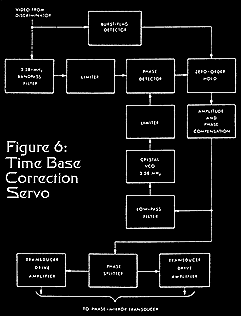 signal corrected all other portions of the video will be correct. The time base correction technique is
illustrated in Fig. 6.
signal corrected all other portions of the video will be correct. The time base correction technique is
illustrated in Fig. 6.
The chrominance signal is extracted from the video and applied as one input to a phase detector. The other
input is derived from a narrow range crystal VCO operating at the nominal color burst frequency. A zero order
hold samples the phase detector output during the burst time-slot. Thus, the output signal has an amplitude
proportional to the phase difference between the video burst signal and the VCO. This signal is then applied
to an amplitude and phase compensation circuit (similar to the tracking servo) to stabilize the servo operation.
The output of the compensation circuit is applied to a phase-splitter and then to the transducer drive
amplifiers. The mirror transducer constantly positions the read beam such that the video burst frequency is
exactly identical to the VCO. Since the mirror transducer has finite dynamic range, static errors must be
corrected by another technique. Another loop has been added to correct this problem. A signal containing the
very low frequency components of the main servo loop is applied to the referenced VCO in a manner to cancel
the static errors. |
3.6 Reading Height Regulation
The videodisc is maintained at the focus of the optical system by means of a vacuum controlled aerodynamic
reading head that carries the objective lens. The thin videodisc is separated from the turntable by a film of
air when the turntable is rotating at speed. This film is due to the radial outward flow of air drawn through
a circle of ventilating holes bored in the turntable just outside of the clamp ring. The air film decreases
the coupling between the videodisc and the turntable enough to permit a vacuum applied to the face of the
reading head to make a bulge in the surface of the thin videodisc.
The distance between the reading head and the surface of the videodisc is stabilized by the balance between
the aerodynamic forces tending to push the disc away from the read head and the vacuum that tends to pull the
disc toward the read head. The separation between the read head and the videodisc is controlled by vacuum
pressure and air flow into the vacuum port on the read head. This fail-safe, vacuum controlled, aerodynamic
reading head operates with a head-to-disc spacing of greater than-1 mil and provides stiff head-to-disc,
coupling that maintains the distance between the objective lens and the thin replicated videodisc to within 1
micrometer which is adequate to keep the optical system in focus. |
3.7 Discriminator and Drop-out Compensator
Because the FM encoded signal recorded on the disc is video in the NTSC format with the sound at 4.5 mHz, the
signal processing electronics can be relatively simple. As shown in Fig. 7, the video signal is first
recovered with a discriminator and then used to modulate an oscillator tuned to an unused TV channel. A more
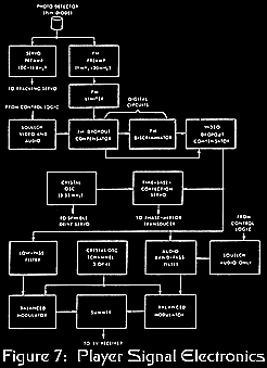 detailed description follows: The FM encoded information from the PIN photodiode is amplified by a wide band,
low noise pre-amp located near the photodiode. The signal is limited and applied to the FM drop-out
compensator.
detailed description follows: The FM encoded information from the PIN photodiode is amplified by a wide band,
low noise pre-amp located near the photodiode. The signal is limited and applied to the FM drop-out
compensator.
Due to the nature of the Disco-Vision record and reproduce process, drop-outs tend to be caused by a missed
half-cycle of the FM carrier. This requires a different compensation technique than that for systems such as
magnetic tape where the duration of the drop-out is generally a large portion of a horizontal line. A missed
half-cycle of carrier looks like a large decrease in instantaneous frequency so that the discriminator produces
a whiter than white impulse in the video signal. If not compensated, the drop-out would produce a very
distracting white spot in the TV image. To reduce the viewers awareness of the dropout, the playback
electronics includes an FM drop-out compensator which detects the missing half-cycle and synthesizes a signal
to replace it. Although it contains no information, the synthetic pulse greatly reduces the visibility of the
drop-out. This entire section, including the multiplying type of discriminator, is implemented with digital
techniques for cost savings and ease of alignment.
On rare occasions drop-outs with a duration of several cycles of carrier are encountered. When this happens
compensation is most easily done in the video domain. This is accomplished by passing the video signal through
a zero order hold which operates normally in the sample mode. When a multiple cycle drop-out is detected, the
circuit is switched to the hold mode. This supplies the last sampled value of luminance signal for the
duration of the drop-out.
After discrimination what results is a full bandwidth NTSC composite signal complete with audio subcarrier.
The Disco-Vision recording and reproducing system, if not limited by the TV receiver, produces an image with
more than 450 lines of horizontal resolution (on the basis of two lines of horizontal resolution per cycle of
video signal) and video signal-to-noise ratio of greater than 40 db in the replica disc. |
3.8 R. F. Modulator
The R. F. modulator is illustrated in a portion of Fig. 2. The audio subcarrier and the video signals are
separated by filters. Each is then applied as one input to a pair of balanced modulators. The other pair of
inputs are derived from an oscillator tuned to the carrier frequency of the unused TV channel selected. The
outputs of the modulators are then sunned to form the RF signal for application to the antenna terminals of a
TV receiver. A switching arrangement linked to the player power switch, connects normal TV antenna to the TV
receiver when the player is not in use. |
3.9 Operating Controls
The operating controls for the playback unit are located in a control panel on the top front left corner of
the unit. The control panel consists of a slide switch to turn the unit on and five push button switches
labeled "play," "stop," "in," "out," and "reject." The power to the playback unit is turned on by the slide
switch. The slide switch also disconnects the television antenna from the television receiver and connects
the television receiver to the playback unit.
The "play" push button is used to initiate the start of the playback sequence. When it is depressed and the
cover on the unit is closed the turntable starts to rotate and the player arm moves to position the read head
over the start of the program on the videodisc. When the turntable is up to speed and the player arm is in
position, the player will automatically play through the entire program on the videodisc unless it is
interrupted by pushing one of the other push buttons. Upon completion of the program the turntable will
automatically stop and the player arm will move clear of the videodisc.
The function of the "stop" push button switch is to stop the motion of the player arm and "freeze" the scene
of the television screen to a single TV frame. This single TV frame will then continue until interrupted by
pushing another button. The audio is suppressed during this stop motion sequence.
The "in" push button switch is used to transplant the player arm in toward the center of the disc at
approximately 100 times the normal playing speed for fast scanning to another part of the program. This fast
scanning continues as long as the push button is depressed or until the program is completed. The function of
the "out" push button switch is similar to the "in" switch except it translates the player arm back toward the
start of the program on the disc. The optical, non-contact nature of the system permits fast scanning to be
performed at will with no wear or degradation of the disc. It may be the ideal way for the consumer to locate
a desired band for playback since even with the 100 times speed up in the fast scan arm translation, picture
content can be recognized on the TV screen.
The function of the "reject" push button is to terminate the program and when depressed will stop the turntable
and move the player arm clear of the videodisc. |
3.10 Special Effects and Applications
Because of the lack of physical contact inherent in this optical system and because information or frames
within the disc may be random accessed very rapidly, many applications in addition to home entertainment are
possible. These include archival storage of documents and facsimiles; audio-visual encyclopedias,
dictionaries, catalogs, etc., that may be accessed immediately on a frame address basis; teaching machine and
educational applications which involve inter-active programming with addressable sub-routines and branching and
many other applications where data, pictures, motion or general audio-video information must be stored
inexpensively and accessed flexibly and rapidly. To this end initial work in frame numbering and coding and
search programming has been carried out. |
3.10.1 Frame Number Encoding
This is accomplished by placing within each vertical interval a coded digital word containing the following:
- Pseudo Random Sync Words
- Parity Check
- Five Decimal Digit Frame Number
- Field I.D.
The information is coded in a self-clocking format to simplify the data recovery process. |
3.10.2 Search Program
The digitally encoded frame identification data is recovered with a self-clocking decoder. The data is stored
in a buffer and updated every vertical interval. A parity check and pseudo random sync codes are used to
ensure only valid data is used. A five digit display presents the number of the frame being viewed.
When the search mode is initiated, logic compares the present frame number with the desired frame number. The
direction in which the desired frame lies is determined, and the leadscrew servo is set into fast scan in that
direction. The digital data is read during the fast scan until passing the desired number. If the initial
scan was in reverse, the leadscrew stops, and the player resumes normal real-time play until the desired frame
is reached. If the initial scan was forward, the leadscrew reverses direction after passing the selected
number and continues until the number is again passed. This places the read beam again behind of the desired
frame. The leadscrew again stops, and normal real-time play is resumed until the desired frame is reached.
When the desired frame is reached, the logic switches to the stop motion mode where the desired frame can now
be viewed. With the present player, this technique permits access to any frame out of about 36,000 within a
fewer seconds. The search logic has the capability to perform other special effects. They are forward and
reverse slow-motion (variable rate), and single-frame step forward and reverse. |